PPP authentication – PAP and CHAP

setup to do PAP on one interface and CHAP on another interface:

R1(config)#do sh run int s0/0
Building configuration…

Current configuration : 154 bytes
!
interface Serial0/0
ip address 12.12.12.1 255.255.255.0
encapsulation ppp
clock rate 2000000
ppp authentication pap
ppp chap password 0 cisco
end

R1(config)#do sh run | i username
username R2 password 0 cisco

R2(config-if)#do sh run int s0/0
Building configuration…

Current configuration : 171 bytes
!
interface Serial0/0
ip address 12.12.12.2 255.255.255.0
encapsulation ppp
clock rate 2000000
ppp authentication chap
ppp pap sent-username R2 password 0 cisco
end

R2(config-if)#do sh run | i username
username R1 password 0 cisco
ppp pap sent-username R2 password 0 cisco

exceed-action policed-dscp-transmit (3560 switch port)

exceed-action policed-dscp-transmit

Must use ACCESS-LIST in class-map when doing this or will not match and/or remark or drop

mls qos map policed-dscp 0 to 46
mls qos
!
class-map match-all ICMP_CM
match access-group name ANY
!
policy-map ICMP_PM
class ICMP_CM
police 8000 8000 exceed-action policed-dscp-transmit
!
interface GigabitEthernet0/1
switchport trunk encapsulation dot1q
switchport mode trunk
service-policy input ICMP_PM
!
ip access-list extended ANY
permit ip any any

SW2#sh mls qos maps policed-dscp
Policed-dscp map:
d1 : d2 0 1 2 3 4 5 6 7 8 9
—————————————
0 : 46 01 02 03 04 05 06 07 08 09
1 : 10 11 12 13 14 15 16 17 18 19
2 : 20 21 22 23 24 25 26 27 28 29
3 : 30 31 32 33 34 35 36 37 38 39
4 : 40 41 42 43 44 45 46 47 48 49
5 : 50 51 52 53 54 55 56 57 58 59
6 : 60 61 62 63

THE SHOW service-policy interface command does not work either use ‘ show mls qos’ commands and look at dscp marking packet counts and IN/OUT of PROFILE:

SW2#sh mls qos interface g0/1 statistics
GigabitEthernet0/1

dscp: incoming
——————————-

0 – 4 : 95083 0 0 0 0
5 – 9 : 0 0 0 0 0
10 – 14 : 0 0 0 0 0
15 – 19 : 0 0 0 0 0
20 – 24 : 0 0 0 0 0
25 – 29 : 0 0 0 0 0
30 – 34 : 0 0 0 0 0
35 – 39 : 0 0 0 0 0
40 – 44 : 0 0 0 0 0
45 – 49 : 0 0 0 201 0
50 – 54 : 0 0 0 0 0
55 – 59 : 0 0 0 0 0
60 – 64 : 0 0 0 0
dscp: outgoing
——————————-

0 – 4 : 47321 0 0 0 0
5 – 9 : 0 0 0 0 0
10 – 14 : 0 0 0 0 0
15 – 19 : 0 0 0 0 0
20 – 24 : 0 0 0 0 0
25 – 29 : 0 0 0 0 0
30 – 34 : 0 0 0 0 0
35 – 39 : 0 0 0 0 0
40 – 44 : 0 0 0 0 0
45 – 49 : 0 0 0 200 0
50 – 54 : 0 0 0 0 0
55 – 59 : 0 0 0 0 0
60 – 64 : 0 0 0 0
cos: incoming
——————————-

0 – 4 : 96226 0 0 0 0
5 – 7 : 0 167 1945
cos: outgoing
——————————-

0 – 4 : 47323 0 0 0 0
5 – 7 : 0 16 185
Policer: Inprofile: 770 OutofProfile: 245757

Locations for bandwidth control and AAR – Automated Alternate and SRST

Locations for bandwidth control and AAR – Automated Alternate

Routing and SRST

Example in a CENTRALIZED CALL MODEL(locations only work in

this model as the CUCM provides call control for all sites)

with CUCM in Dallas and remote office in Little Rock with all

VOIP phones getting signalling from Dallas CUCM and calls

using the WAN bandwidth need to control the bandwidth that is

allowed calls, we will say WAN is 768Kpbs connection

Create 2 locations:

Dallas – Audio Bandwidth 768Kpbs
Little Rock – Audio Bandwidth 768Kbps

Then assign phones to location Dallas or Little Rock

Calls between phones in same location do not subtract from

total only calls between different locations

G.711 subtracts 80Kbps(64Kpbs plus overhead)
G.723 subtracts 24Kpbs
G.729 subtracts 24Kpbs
On average CUCM adds 16Kpbs for overhead to codec for CAC

(Call Admimission Control)

Another example with 3 locations:

Dallas has 45Mb
Little Rock has 768Kbps
Atlanata has 1.5Mbps

Setup for locations as follows:
Dallas Audio Bandwidth Unlimited (compared to other sites

with less bandwidth)
Little Rock stays at 768Kbps
Atlanta 1500Kbps

DISTRIBUTED CALL-PROCESSING MODEL:
need to use Independent WAN bandwidth control using H.323

Gatekeeper or SIP Proxy, meaning that it is not under control

of any CUCM cluster, gatekeeper can be linux box or other

application running on another OS

AAR – Automated Alternate Routing
CENTRALIZED CALL MODEL

1. Configure External Phone Number Mask – this is the mask

that will be added to the extension number for the PSTN to

see, also is display on phone

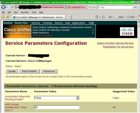
2. Configure Service parameters and AAR Groups – Like

‘registry’ for call manager change Automated Alternate

Routing Enable* to True also add to

Out-of-Bandwidth Text* message to say “Please Try Again

Later” (only allowed 23 characters in 4.x) to avoid calls of

panic NO BANDWIDTH, also AAR Network Congestion Rerouting

Text*
AAR Groups – Prefix Digits to add between locations for

example 9 for PSTN calls local or 91 for PSTN long distance

3. Configure DN to use AAR Group – Under device line

configuration add AAR Group

4. Configure AAR CSS – AAR Calling Search Space Under device

configuration, need to give access to Long Distance PSTN CSS

SRST on Remote Routers:

1. Call-Manager-Fallback
2. IP Source-address
3. Max-Ephones (what you have a license for)
4. Max-DN

SRST on Call Manager (CUCM):

1. under Device Pool Configuration SRST Reference field (if

not using Default Gateway) configure SRST Reference under

System SRST

For FULL SRST dialing would need to setup Dial Peers on the

SRST Router for complete dialing

P1

Spanning Tree port roles pvst and rapid-pvst ‘show spanning-tree’

Spanning Tree switches

Spanning Tree switches

Working to get all the rapid-pvst port roles to show up in output of ‘show spanning-tree’ command, got that to work but noticed that these same roles show up in the pvst(ieee) output as well…

I believe this is just a cli output issue, as the states still process correctly (lis, lrn, fwd)

The diagram shows the 2 switches with a “loopback” cable (port g0/51 – g0/52) causing the BACKUP port role to show up as I did not have a real hub and needed the switch bpdu to return to itself to cause this BACKUP port role…

CLI OUTPUT from top switch NATIVE_4 and the ROOT switch NATIVE_2:

NATIVE_4#sh spanning-tree
VLAN0001
Spanning tree enabled protocol ieee
Root ID Priority 32769
Address 0021.1bf4.bd00
Cost 4
Port 1 (GigabitEthernet0/1)
Hello Time 2 sec Max Age 20 sec Forward Delay 4 sec
Bridge ID Priority 32769 (priority 32768 sys-id-ext 1)
Address 0022.0c4f.1c00
Hello Time 2 sec Max Age 20 sec Forward Delay 15 sec
Aging Time 300
Interface Role Sts Cost Prio.Nbr Type
—————- —- — ——— ——– ——————————–
Gi0/1 Root FWD 4 128.1 P2p
Gi0/48 Altn BLK 4 128.48 P2p
Gi0/51 Desg FWD 4 128.51 P2p
Gi0/52 Back BLK 4 128.52 P2p

NATIVE_2#sh spanning-tree
VLAN0001
Spanning tree enabled protocol ieee
Root ID Priority 32769
Address 0021.1bf4.bd00
This bridge is the root
Hello Time 2 sec Max Age 20 sec Forward Delay 4 sec
Bridge ID Priority 32769 (priority 32768 sys-id-ext 1)
Address 0021.1bf4.bd00
Hello Time 2 sec Max Age 20 sec Forward Delay 4 sec
Aging Time 300 sec
Interface Role Sts Cost Prio.Nbr Type
——————- —- — ——— ——– ——————————–
Gi0/1 Desg FWD 4 128.1 P2p
Gi0/48 Desg FWD 4 128.48 P2p

method to “calculate” 6to4 tunnel address

http://www.cisco.com/en/US/docs/ios/ipv6/configuration/guide/ip6-addrg_bsc_con_ps6441_TSD_Products_Configuration_Guide_Chapter.html#wp1133726

Method to “calculate” 6to4 tunnel address.
Command was introduced: 12.3(4)T
!
interface Loopback0
ip address 157.1.1.1 255.255.255.0
!
R1(config)#ipv6 unicast-routing
R1(config)#ipv6 general-prefix myPref 6to4 loop0
R1(config)#do sh ipv6 general-prefix
IPv6 Prefix myPref, acquired via 6to4
2002:9D01:101::/48
R1(config)#

Converting IPv4 to IPv6 and back

http://blog.ru.co.za/2009/03/19/converting-ipv4-to-ipv6/

Converting from IPv4 to IPv6
is so easy, yet everyone seem to convert a IPv4 address to binary, then to IPv6. Why? Why waste time and do things the long way? Not cool.

When would you need to do this? One specific use is IPv6 6-to-4 tunnels, which always concatenates 2002::/16 with the IPv4 address embedded.
With Automatic 6-to-4-tunnels, your address format is as follow:
2002::::/64

The question is how to do the conversion.

Firstly before starting I will assume everyone knows the following:

Binary is a Base-2 numbering system, as it has only 0,1
Decimal is a Base-10 numbering system, as it has 0,1,2,3,4,5,6,7,8,9
Hexadecimal is a Base-16 numbering system, as it has 0,1,2,3,4,5,6,7,8,9,A,B,C,D,E,F
I also assume you know the hex values in decimal:

A = 10
B = 11
C = 12
D = 13
E = 14
F = 15
Two more things I would like to mention before explaining the conversion.
An IPv4 address : example 192.168.99.1

Each Octet (8 bits) “between the dot-thingys” denote 1 byte
An IPv6 address : example 2001:0db8:85a3:0000:0000:8a2e:0370:7334

Two Tuples (1 Tuple = 4 bits = 1 Hex character) denotes 1 byte
Then converting is easy. Lets take the following IPv4 address : 192.168.99.1 and convert it to Hex.

Step1 >

Divide the first octet (192) by 16 (since Hex is a Base-16)
IE : 192/16 = 12 times exactly with 0 left over
– 12 in Hex is represented as C
– 0 (zero) in Hex is, you guessed it, 0
Thus 192 in HEX is C0

Step2 >

Repeat step 1 with the second octet (168),
IE : 168/16 = 10 times with 8 left over because 10*6 = 160,
– 10 in HEX is A
– 8 in HEX is 8
Thus 168 in HEX is A8

Step3 >

Repetition rules!!! Third octet (99)
IE : 99/16 = 6 times with 3 left over
– 6 in HEX is 6
– 3 in HEX is 3
Thus 99 in HEX is 63

Step4 >

Last octet
IE : 1/16 = 0 times with 1 left over
– 0 in HEX is, yeah it is 0
– 1 in HEX is 1
Thus 1 in HEX is 01

So the IPv4 address of 192.168.99.1, represented in the IPv6 address portion would be C0A8:6301.
So when using IPv6 6-to-4 Tunnels, on the one endpoint of the tunnel, with the IPv4 address of 192.168.99.1, the complete IPv6 address would be 2002:C0A8:6301::1/64
See, not all that difficult, if you know your 16 multiplication table, you can do this in your head, no problems.

– – – –

.

Converting back from IPv6 to IPv4
Now to convert the same portion of the IPv6address 2002:C0A8:6301::1/64 back to IPv4, the reverse method would apply.

Let me point one more thing about Base-16 out to understand why I’m doing what I am below:

160 = 1

161 = 16

Taking the portion C0A8:6301, first divide the address into 2 Tuple-groupings (2 Hex Characters) = C0 A8 63 01

Step1 >

Take C0 and multiply the first character ‘C’ by 16 and the second character ’0′ by 1.
Add the two decimal values together to get the IPv4 decimal value
IE: ((C=12)*16) + (0*1) = 192

Step2 >

Repeat the same process with A8,
IE: ((A=10)*16) + (8*1) = 168

Step3 >

Repeat the same process with 63,
IE: (6*16) + (3*1) = 99

Step4 >

Repeat the same process with 01,
IE: (0*16) + (1*1) = 1

This will give you an IPv4 address of 192.168.99.1

Easy, easy!

ip pim rp-address ‘ip address’ override

R2 R1

R2:
interface Serial0/0
ip address 183.1.123.2 255.255.255.0
ip authentication mode eigrp 100 md5
ip authentication key-chain eigrp 100 EIGRP
ip pim sparse-mode
encapsulation frame-relay
no ip split-horizon eigrp 100
clock rate 2000000
no arp frame-relay
frame-relay map ip 183.1.123.1 201 broadcast
frame-relay map ip 183.1.123.3 203 broadcast
no frame-relay inverse-arp

interface Loopback0
ip address 100.2.2.2 255.255.255.0
ip pim sparse-mode
ip igmp join-group 239.1.1.1

no ip pim dm-fallback
ip pim bsr-candidate Serial0/0 0
ip pim rp-candidate Serial0/0

R2#sh ip pim bsr-router
PIMv2 Bootstrap information
This system is the Bootstrap Router (BSR)
BSR address: 183.1.123.2 (?)
Uptime: 00:07:24, BSR Priority: 0, Hash mask length: 0
Next bootstrap message in 00:00:14
Candidate RP: 183.1.123.2(Serial0/0)
Holdtime 150 seconds
Advertisement interval 60 seconds
Next advertisement in 00:00:05

R2#sh ip pim rp
Group: 239.1.1.1, RP: 183.1.123.1, v2, uptime 00:04:04, expires 00:02:24

R1:
interface Serial0/0
ip address 183.1.123.1 255.255.255.0
ip authentication mode eigrp 100 md5
ip authentication key-chain eigrp 100 EIGRP
ip pim sparse-mode
encapsulation frame-relay
clock rate 2000000
no arp frame-relay
frame-relay map ip 183.1.123.2 102 broadcast
frame-relay map ip 183.1.123.3 102
no frame-relay inverse-arp
no ip pim dm-fallback
ip pim bsr-candidate Serial0/0 0
ip pim rp-candidate Serial0/0

R1#sh ip pim bsr-router
PIMv2 Bootstrap information
BSR address: 183.1.123.2 (?)
Uptime: 00:03:53, BSR Priority: 0, Hash mask length: 0
Expires: 00:01:17
This system is a candidate BSR
Candidate BSR address: 183.1.123.1, priority: 0, hash mask length: 0
Candidate RP: 183.1.123.1(Serial0/0)
Holdtime 150 seconds
Advertisement interval 60 seconds
Next advertisement in 00:00:25

R1(config)#ip pim rp-address 100.2.2.2
R1(config)#do sh ip pim rp
Group: 239.1.1.1, RP: 183.1.123.1, v2, next RP-reachable in 00:01:00
Group: 224.0.1.40, RP: 100.2.2.2, uptime 00:00:05, expires never

R1(config)#ip pim rp-address 100.2.2.2 override
R1(config)#do sh ip pim rp
Group: 239.1.1.1, RP: 100.2.2.2, uptime 00:00:02, expires never
Group: 224.0.1.40, RP: 100.2.2.2, uptime 00:00:21, expires never